- defining constants
`define N_TYPE -1
`define P_TYPE +1
`define PI 3.14159265358979323846
...
`define SILICON_PERMITTIVITY 1.0359431e-10
- you have to use the following construct in order to use this example in other simulators
The (*...*) properties are used bu ADMS to build the c code of the model.
- declaration of MOS1
module MOS1 ( Drain, Gate, Source, Bulk );
inout Drain, Gate, Source, Bulk;
- special attributes for node names to save node voltages by convenient Spice names
electrical Drain `P(spice:name="d"), Gate `P(spice:name="g"), Source `P(spice:name="s"), Bulk `P(spice:name="b");
electrical IntDrain, IntSource;
parameter integer GENDER = `N_TYPE;
- special attributes with names, decriptions, types (model or instance), default values and units for parameters
parameter real L = 3.0e-6 `P(spice:name="l" info="Default channel length" type="instance" unit="m");
parameter real W = 3.0e-6 `P(spice:name="w" info="Default channel width" type="instance" unit="m");
...
parameter real VTOTEMPCOEF = 0 `P(spice:name="vtotempcoef" info="Threshold voltage temperature coefficient" type="instance");
- local variables declaration
integer Reversed;
real Vd, Vs, Vb, Vds, Vgs, Vbs, Vbd;
real Vt, Von, Vth, Vdsat, Vgst, Vc, Vfb, Vto;
real Iss, Idd, Ibs, Ibd, Irs, Ird, Ibulk, Ioffset, Id;
...
real Vexpl, Gexpl;
- special construct used to declare output variables
- begining of analog block
- intialization blocks for model and instance parameters which contains common mosfet equations
`ifdef insideADMS
@(initial_model)
`endif
begin
...
end
`ifdef insideADMS
@(initial_instance)
`endif
begin
...
end
- skiping some equations
- evaluation of the model equations
/* Thershold voltage */
Vth = Vto + Gamma * ( T1s - sqrtPhi );
Vgst = Vgs - Vth;
Vdsat = Vgst;
/* Drain current */
if( Vgst > 0 )
if ( Vgst >= Vds )
begin
betta = Kp * Weff / Leff;
Ids = betta * ( Vgst - Vds / 2.0 ) * Vds * ( 1 + Lambda * Vds );
end
else
begin
betta = Kp * Weff / Leff;
Ids = betta * Vgst * Vgst / 2.0 * ( 1 + Lambda * Vds );
end
/* For P_TYPE */
if( GENDER == `P_TYPE )
begin
Vth = -Vth;
Ids = -Ids;
end
- output
if ( RD > 0.0 )
I(Drain, IntDrain) <+ V(Drain, IntDrain)/RD;
else
I(Drain, IntDrain) <+ V(Drain, IntDrain);
if ( RS > 0.0 )
I(Source, IntSource) <+ V(Source, IntSource)/RS;
else
I(Source, IntSource) <+ V(Source, IntSource);
I(IntDrain, IntSource) <+ Ids;
-end of analog block
-end of module
Full code version available at here |back to top|
Verification |back to top|
After implementation of device mos1.va into ZSPICE you'll get mos1.zsp file ( translation order you can see if you type zspice -h ).
Command zspice --load mos1 shows you that model connected to zspice.
For verification you need to create a simple testcase such as:
mode=circuit
name=dc_Vg_Vd
mode=load
file=mos1.zsp
mode=model
name=mymos1
module=mos1
mode=parameter
name=GENDER
value=-1
mode=model
name=vsource
module=vs
mode=instance
name=mos1
modelID=mymos1
mode=topology
mode=node
name=d
location=1
mode=node
name=g
location=2
mode=node
name=s
location=0
mode=node
name=b
location=0
mode=instance
name=vg
modelID=vsource
mode=parameter
name=dc
value=1.0
mode=topology
mode=node
name=p
location=2
mode=node
name=n
location=0
mode=instance
name=vd
modelID=vsource
mode=parameter
name=dc
value=3
mode=topology
mode=node
name=p
location=1
mode=node
name=n
location=0
mode=dc
mode=sweep
name=vg:dc
start=0.0
end=5.0
step=0.1
mode=save
name=mos1:Ids
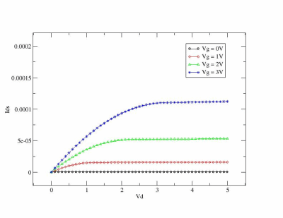
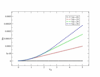
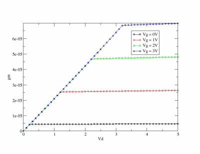
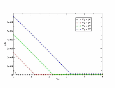
If you run some tests and parse output you can see theese graphics: |back to top|
 
 
You can use simple Perl script which parse zspice output and run xmgrase to create such images :)
Links to Related Projects: |back to top|
|


